


Overset Mesh -- New technology in ANSYS FLUENT
- 2016年9月13日
- 讀畢需時 2 分鐘
Introduction
In the latest version of ANSYS FLUENT (17R), users are allowed to build up the computational fomain from overlapping meshes ---- also known as Chimera or overset methodology. For those of you who are familiar with STAR-CCM, the word 'overset' might not be new to you. It gives you another option to build the complete mesh, in addition to using conformally connected cell zones, non-conformal interfaces, and mapped mesh interfaces.
Limitation
Because it is a relatively new feature in ANSYS FLUENT, it is not compatible with all existing utilities. Only the following models and methods are supported so far:
1) Steady and transient (fixed mesh), 3D and 2D planar;
2) Pressure Based coupled solver;
3) Incompressible density method;
4) Single-phase or VOF multiphase;
5) Heat transfer;
6) k-epsilon and SST k-ω turbulence models;
7) BETA: moving mesh, compressible flow, VOF with surface tension, pressure-far-field BC,Workbench support, Pressure-Based segregated algorithms.
If your problem could be solved by the models mentioned above, then you can continue on the rest of this blog.
Tutorial
This brief tutorial shows you how you can generate the mesh and create a overset mesh interface in ANSYS FLUENT. The model we use here is a classic 2D model: flow around a cylinder. The computation domain is chosen to be a rectangular and the cylinder is located at the center of our domain.
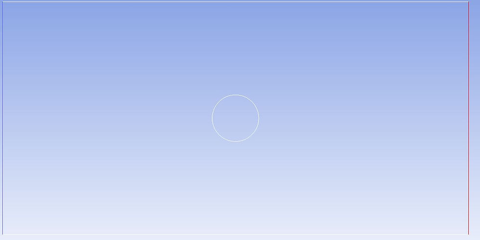
In order to have one layer of mesh overlaps on another layer, you need at least two cell zones in your model. Thus, we first make the central cylinder invisible and create a simple structured mesh in the rectangular domain:
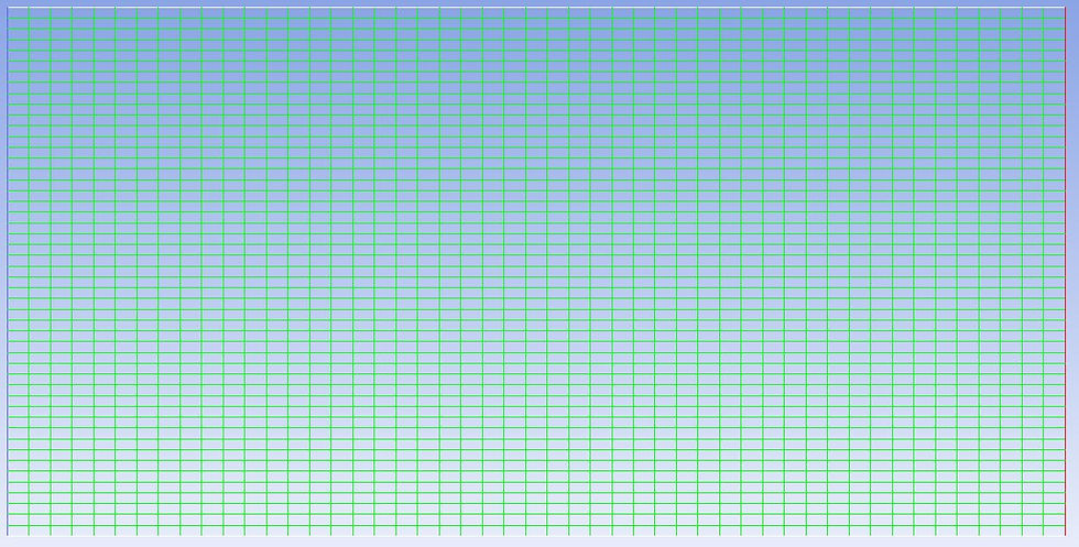
This is what people call background mesh. After that, disable everything on the screen and enable the cylinder. Create the mesh around the cylinder:

Remember that the mesh should be assigned to a different zone (or part) otherwise you would be unable to create the overset interface in FLUENT. This is what we call overset mesh.
Now, you can just import the mesh in the same way as you did for ordinary mesh file. Set the boundary conditions as usual.
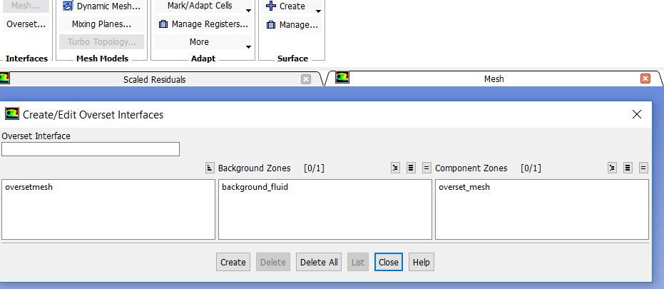
An additional step is needed here before setting the solver options. You need to change the boundary type of the overset mesh peripheral to overset interface. After that, the overset mesh interface will be activated and you can easily create one by selecting the background and the overset, just like what you did in sliding mesh interface:
Now, perform solution setup as usual and you are ready to go! The simulation should converge in 200 iterations. Here is the pressure distribution I got:
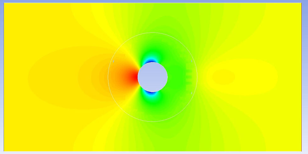
Looks pretty nice and I can't tell any big difference between this and that from a classical connected mesh.
留言